- 您现在的位置:买卖IC网 > Sheet目录238 > NUP45V6P5T5G (ON Semiconductor)TVS QUAD ARRAY LOW CAP SOT-953
NUP45V6P5
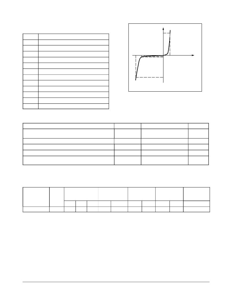
ELECTRICAL CHARACTERISTICS
(T A = 25 ° C unless otherwise noted)
Symbol Parameter
I PP
Maximum Reverse Peak Pulse Current
V C
Clamping Voltage @ I PP
I F
I
I R V F
V RWM
I R
Working Peak Reverse Voltage
Maximum Reverse Leakage Current @ V RWM
V C V BR V RWM
I T
V
V BR
I T
Breakdown Voltage @ I T
Test Current
Q V BR
I F
V F
Z ZT
I ZK
Z ZK
Maximum Temperature Coefficient of V BR
Forward Current
Forward Voltage @ I F
Maximum Zener Impedance @ I ZT
Reverse Current
Maximum Zener Impedance @ I ZK
I PP
Uni ? Directional
MAXIMUM RATINGS (T A = 25 ° C unless otherwise noted)
Characteristic
Thermal Resistance Junction ? to ? Ambient
Above 25 ° C, Derate
Maximum Junction Temperature
Operating Junction and Storage Temperature Range
Lead Solder Temperature (10 seconds duration)
Human Body Model (HBM)
Machine Model (MM)
Symbol
R q JA
T Jmax
T J T stg
T L
ESD
Value
560
4.5
150
? 55 to +150
260
8000
400
Unit
° C/W
mW/ ° C
° C
° C
° C
V
Stresses exceeding Maximum Ratings may damage the device. Maximum Ratings are stress ratings only. Functional operation above the
Recommended Operating Conditions is not implied. Extended exposure to stresses above the Recommended Operating Conditions may affect
device reliability.
ELECTRICAL CHARACTERISTICS (T A = 25 ° C)
Device
Breakdown Voltage
V BR @ 1 mA (Volts)
Leakage Current
I RM @ V RM
Typ Capacitance
@ 0 V Bias (pF)
(Note 1)
Typ Capacitance
@ 3 V Bias (pF)
(Note 1)
V C (V)
@ I PP = 1 A
(Note 2)
Device
NUP45V6P5
Marking
5
Min
5.3
Nom
5.6
Max
5.9
V RWM
3.0
I RWM ( m A)
1.0
Typ
13
Max
17
Typ
7.0
Max
11.5
Max
10.5
1. Capacitance of one diode at f = 1 MHz, T A = 25 ° C.
2. Surge current waveform per Figure 3.
http://onsemi.com
2
发布紧急采购,3分钟左右您将得到回复。
相关PDF资料
NUP46V8P5T5G
TVS QUAD ARRAY LOW CAP SOT-953
NUP5120X6T2G
IC TVS ARRAY 5LINE SOT-563
NUP5150MUTBG
IC TVS ARRAY 5LINE ESD 6-UDFN
NUP6012PMUTAG
TVS ESD 6CH LOW CAP 6-UDFN
NUP6101DMR2
IC TVS ARRAY UNIDIR 300W 8MICRO
NUP8010MNT1G
IC TVS ARRAY LO CAP DFN8
NWE115DHHN-T921
CONN PCI EXPRESS 230POS VERT PCB
NWE82DHRN-T941
CONN PCI EXPRESS 164POS VERT PCB
相关代理商/技术参数
NUP46V8P5
制造商:ONSEMI 制造商全称:ON Semiconductor 功能描述:Low Capacitance Quad Array for ESD Protection
NUP46V8P5T5G
功能描述:TVS二极管阵列 HANA SEMI TH2 SOT953 RoHS:否 制造商:Littelfuse 极性: 通道:4 Channels 击穿电压: 钳位电压:11.5 V 工作电压:2.5 V 峰值浪涌电流:20 A 安装风格:SMD/SMT 端接类型:SMD/SMT 系列: 最小工作温度:- 40 C 最大工作温度:+ 85 C
NUP5120/D
制造商:未知厂家 制造商全称:未知厂家 功能描述:5-Line Transient Voltage Suppressor Array
NUP5120X6
制造商:ONSEMI 制造商全称:ON Semiconductor 功能描述:5−Line Transient Voltage Suppressor Array
NUP5120X6T1
功能描述:TVS二极管阵列 5 Line Suppressor RoHS:否 制造商:Littelfuse 极性: 通道:4 Channels 击穿电压: 钳位电压:11.5 V 工作电压:2.5 V 峰值浪涌电流:20 A 安装风格:SMD/SMT 端接类型:SMD/SMT 系列: 最小工作温度:- 40 C 最大工作温度:+ 85 C
NUP5120X6T1G
功能描述:TVS二极管阵列 5 Line Suppressor Array RoHS:否 制造商:Littelfuse 极性: 通道:4 Channels 击穿电压: 钳位电压:11.5 V 工作电压:2.5 V 峰值浪涌电流:20 A 安装风格:SMD/SMT 端接类型:SMD/SMT 系列: 最小工作温度:- 40 C 最大工作温度:+ 85 C
NUP5120X6T2
功能描述:TVS二极管阵列 5 Line Suppressor RoHS:否 制造商:Littelfuse 极性: 通道:4 Channels 击穿电压: 钳位电压:11.5 V 工作电压:2.5 V 峰值浪涌电流:20 A 安装风格:SMD/SMT 端接类型:SMD/SMT 系列: 最小工作温度:- 40 C 最大工作温度:+ 85 C
NUP5120X6T2G
功能描述:TVS二极管阵列 5 Line Suppressor Array RoHS:否 制造商:Littelfuse 极性: 通道:4 Channels 击穿电压: 钳位电压:11.5 V 工作电压:2.5 V 峰值浪涌电流:20 A 安装风格:SMD/SMT 端接类型:SMD/SMT 系列: 最小工作温度:- 40 C 最大工作温度:+ 85 C
